4-channel RTD input
The module provides RTD1 through RTD4 and supports PT100 or PT1000 sensors through 3-wire or 4-wire model options.


N504x provides 4 RTD input channels for PT100 or PT1000 sensors. Depending on the model, connect 3-wire or 4-wire sensors through RTD1 to RTD4.
Each channel input is electrically isolated and converted to a digital signal with 15-bit resolution, ±1°C accuracy under the stated cable condition, and a 400 ms conversion rate.
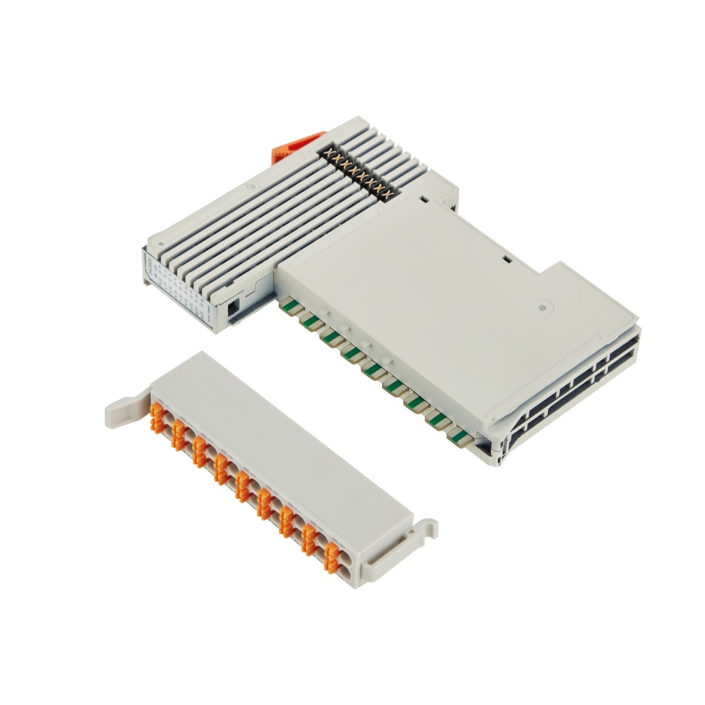
RTD input types, measurement ranges, resolution, accuracy, conversion rate, wiring requirements, environmental ratings, dimensions, terminal definitions, and distributed I/O system requirements.
N5041/N5042 are 3-wire RTD models, while N5043/N5044 are 4-wire RTD models. PT100 and PT1000 variants are available in both wiring types.
| Selection point | 3-wire models | 4-wire models |
|---|---|---|
| Models | N5041 / N5042 | N5043 / N5044 |
| Sensor type | PT100 / PT1000 | PT100 / PT1000 |
| Channels | 4 channels | 4 channels |
| Resolution | 15 Bit | 15 Bit |
| Conversion rate | 400 ms | 400 ms |
RTD input, conversion, power, and indication data for the N504x series.
Connection and mounting data for the N504x module.
Operating limits and protection information stated in the manual.
Physical dimensions and distributed I/O system requirements.
The module provides RTD1 through RTD4 and supports PT100 or PT1000 sensors through 3-wire or 4-wire model options.
Each channel input is electrically isolated before conversion into a digital signal transmitted with 15-bit resolution.
N504x is an optional N-Series I/O module and must be combined with a suitable coupler, such as a BL210 Series coupler.
N504x combines four isolated RTD input channels, PT100/PT1000 options, 15-bit resolution, ±1°C specified accuracy, a 400 ms conversion rate, cage-clamp wiring, and stated EMC protection.
Connect RTD1 through RTD4 in one 15.4 mm-wide module.
Select N5041/N5042 for 3-wire sensors or N5043/N5044 for 4-wire sensors.
RTD input signals are converted to digital values with 15-bit resolution and a 400 ms conversion rate.
IP20 protection, IEC 61000-4-2 and IEC 61000-4-5 Level 2 EMC, and -20°C to 55°C operation.
N5041 is 3-wire PT100, N5042 is 3-wire PT1000, N5043 is 4-wire PT100, and N5044 is 4-wire PT1000. Every model provides four RTD channels.
N5041 / N5042 · 3-Wire RTD
N5041 supports 3-wire PT100 and N5042 supports 3-wire PT1000. Both models provide 4 RTD input channels with 15-bit resolution and a 400 ms conversion rate.
Use the FC, RTD, NC, and PE terminal definitions for the selected wiring type, and install the module on a compliant DIN-35 rail as part of the distributed I/O station.
The N-Series includes digital input, digital output, analog input, analog output, RTD, temperature, pulse, and power modules.
I/O modules can be arranged in different combinations within the distributed I/O station without grouping them by module type.
6 modules
Digital input options for NPN, PNP, and dry-contact sensing.
5 modules
Digital and relay output options for discrete control.
3 modules
Analog input options for current and voltage acquisition.
2 modules
Analog output options for current and voltage control.
4 modules
RTD modules for PT100 and PT1000 temperature sensing.
2 modules
Dedicated temperature modules for NTC and thermocouple signals.
3 modules
Pulse counting and pulse-output control modules.
1 module
Additional power support for larger N-Series stations.
When the number of selected N-Series I/O boards exceeds 20, an additional power module is required. If the number is less than 20, no extra power module is needed.
The manual specifies the installation sequence, module insertion and removal procedure, cable selection rules, and wiring examples for N5041 through N5044.
Mount the coupler and I/O modules on a DIN 35 rail compliant with IEC 60715, then assemble modules from the fieldbus coupler left to right.
Align the spring contact with the groove, keep the rail clip unlocked, press the module into position until it snaps onto the rail, and lock the rail clip.
Use a flat-head screwdriver or similar tool to pry the rail clip upward, then pull the I/O module away from the DIN rail.
Cage clamps accept solid, stranded, and fine-stranded conductors. Use one conductor per clamp, 0.3 to 2.5 mm² / AWG 22 to 14, with an 8 to 9 mm strip length.