Beremiz is an open-source PLC (Programmable Logic Controller) development software, specifically designed for programming and debugging industrial automation control systems. It supports the IEC 61131-3 standard and provides engineers and developers with powerful tools to create, test, and deploy control logic.
Case Details
I. Beremiz Software Installation
1. Download the latest Windows installer from the official site (https://github.com/beremiz/beremiz/releases).
2. After installation, you can open and use it directly. You can uninstall the software using the Uninstall program.
3. For the Linux version, please refer to the official documentation (https://github.com/beremiz/beremiz).
II. OpenPLC Client Software Installation
1. Place the installation files onto the device.
2. Grant permissions to the installation folder, and run the installation script within that folder.
chmod -R +x /OpenPLC_v3
cd /usr/demo/OpenPLC_v3 # Enter the installation folder (adjust according to your device path)
./install.sh linux # Run the installation script and select the Linux environment
The installation script will automatically compile and install the software. An internet connection is required during the installation process. After installation, OpenPLC will be automatically added to the system startup.
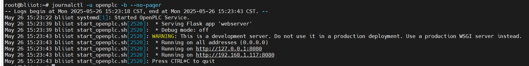
After installation, restart the device and check whether OpenPLC is running successfully by entering:
journalctl -u openplc -b --no-pager
If the service is running normally, the following information will appear.
Usage of Beremiz software
1.Since the default file name used by our OpenPLC client is different from the default file name generated by Beremiz, you need to modify the default file name generated by Beremiz first.
(1) Open the file located in the software installation path.
(2) Find the function AddProjectDefaultConfiguration in the file and modify it as shown below.
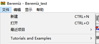
2. Create an empty folder. Open the software, create a new project, and select the empty folder created earlier as the project directory.
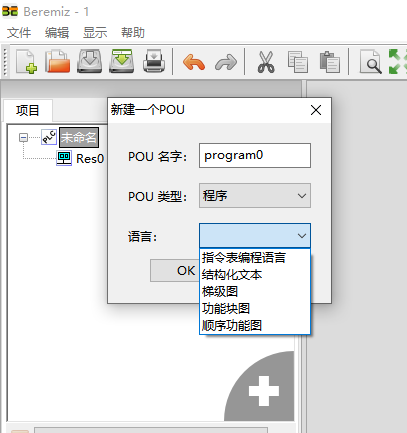
3. Select the programming language you need to use (taking the ladder diagram as an example)
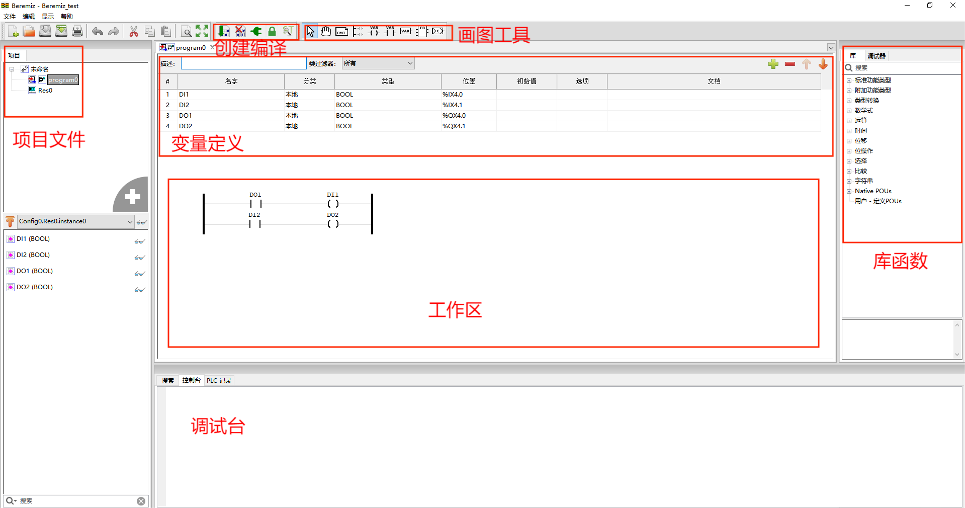
4. The introduction to the user interface is as shown in the figure below:
5. After completing the program writing, click the Build File button to compile.
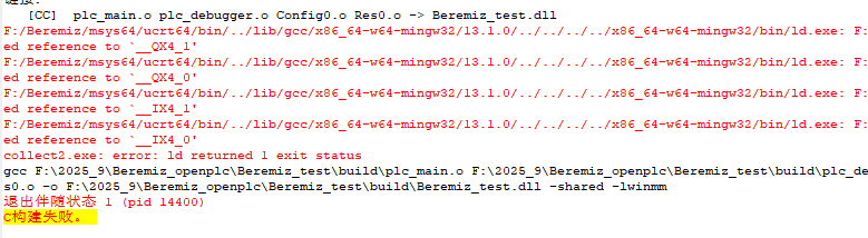
6. After clicking Compile, the following error may occur during linking, indicating that the location of the referenced variable is undefined. However, the PLC program we need has already been generated in the project folder.
Run the PLC program on the device
1. Ensure that the device is connected to the network cable and has obtained the correct IP. Enter ifconfig to check the current IP of the device, for example
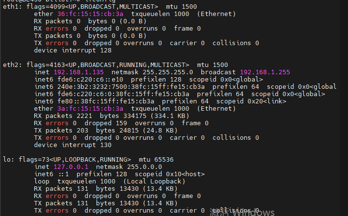
The currently plugged-in network cable is connected to the eth2 port. My IP address is 192.168.1.135. Let's remember this IP address. Open the browser on your computer. Note: Your computer and the device must be on the same network segment to access correctly. Enter 192.168.1.135:8080 in the browser. (Note: The IP address here is the IP of your device; the one entered here is the IP of my device.)
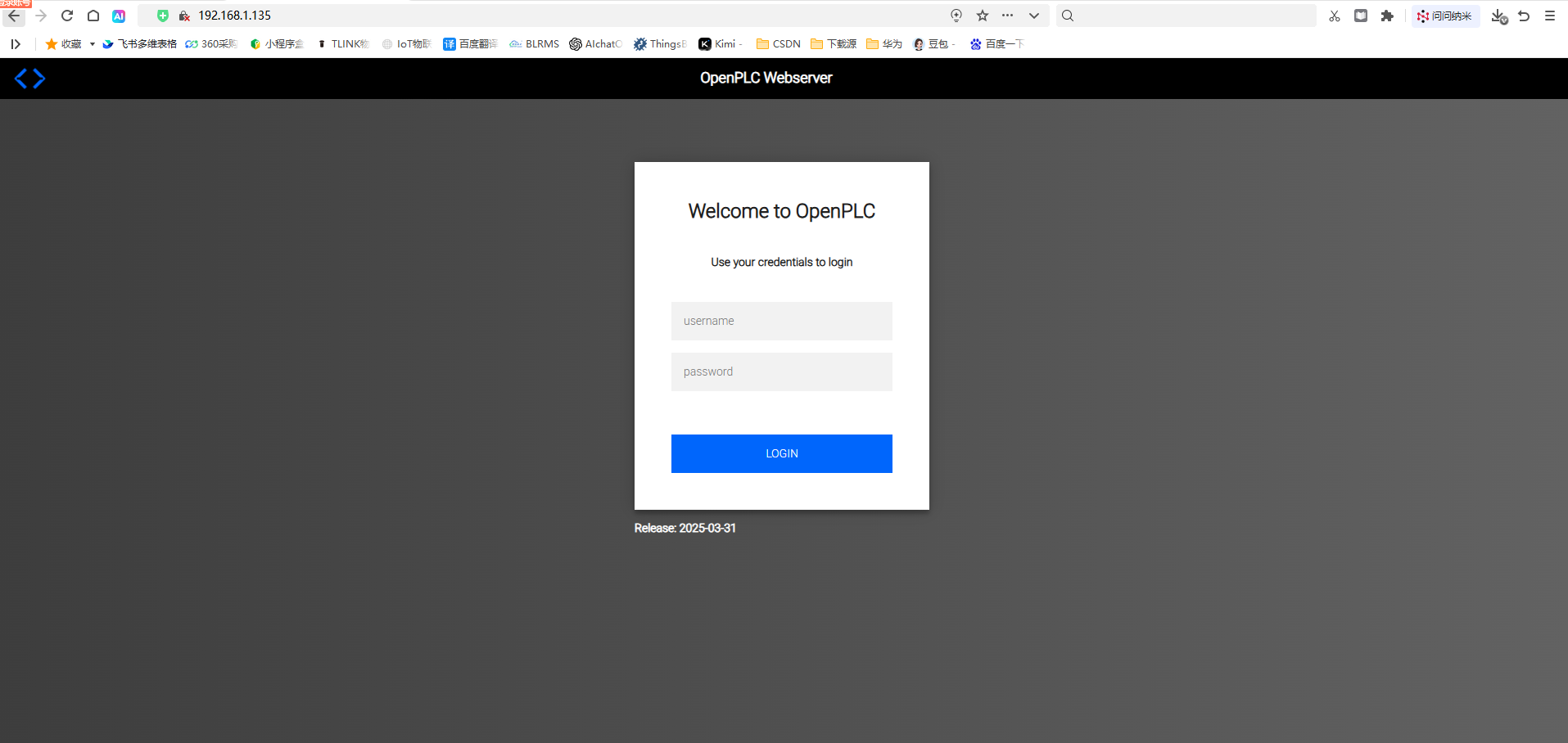
Here we enter the login interface of openplc. We log in with the default user of openplc. User: openplc, Password: openplc
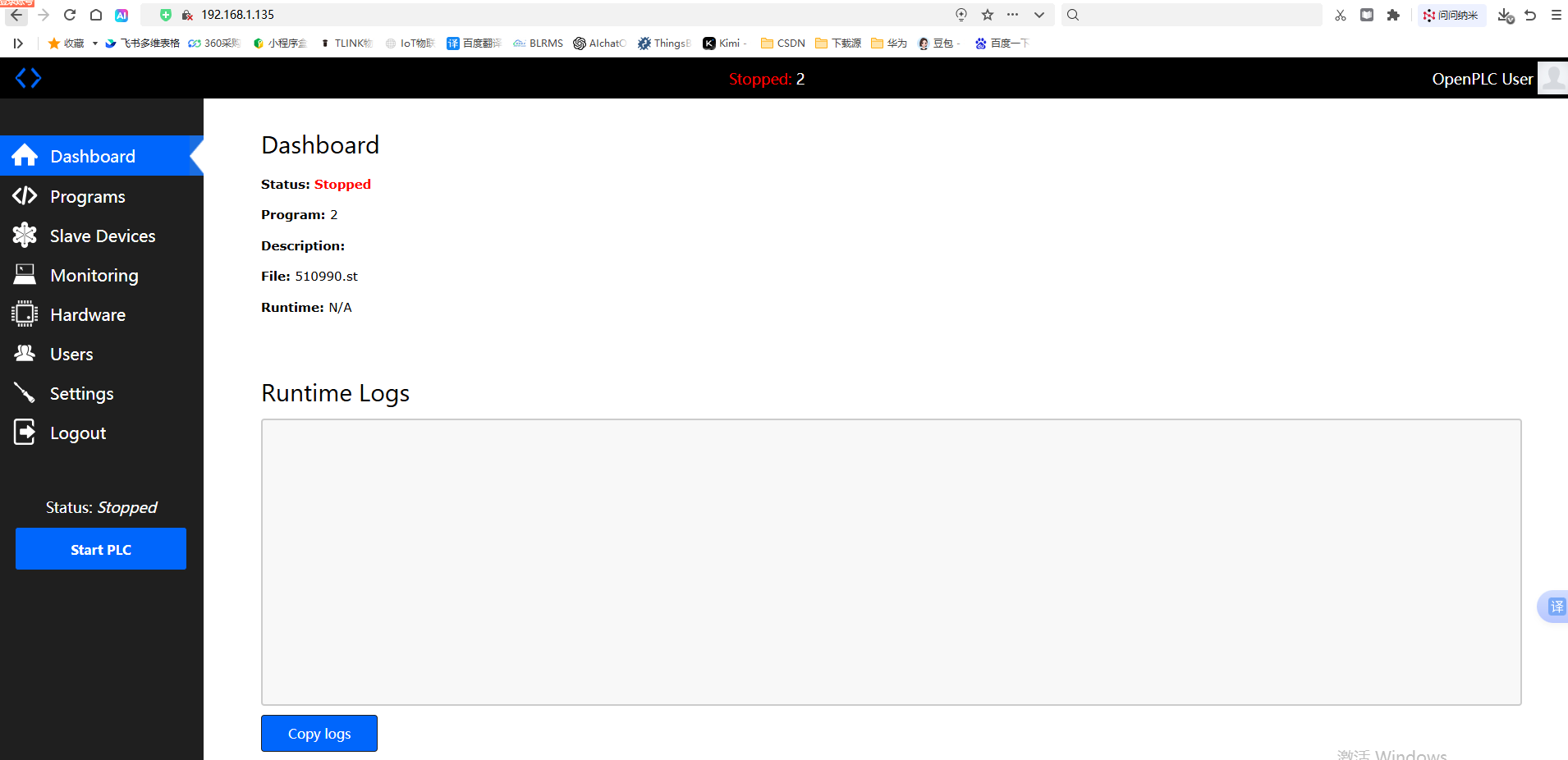
We have successfully logged into the PLC, and now we can start the steps to upload the program and configuration.
2.Select programs to enter the program upload interface
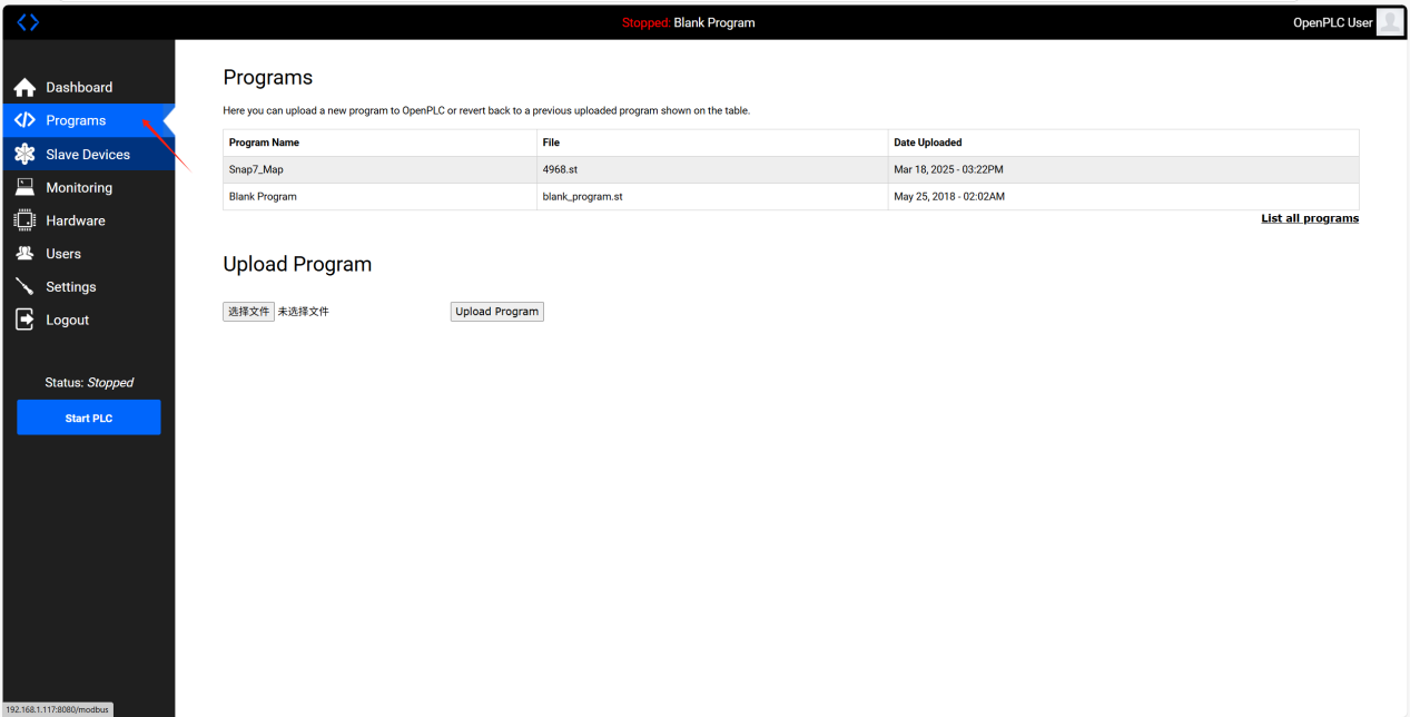
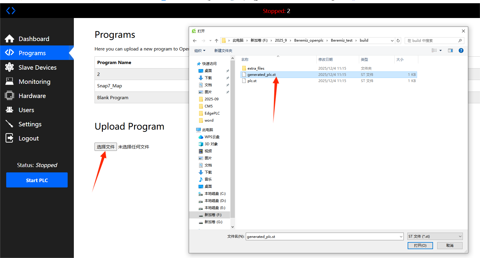
3. Click "Select File" at the bottom left corner of the page and select the PLC program to upload.
4. At this point, we click the upload program button again to enter the program info page.
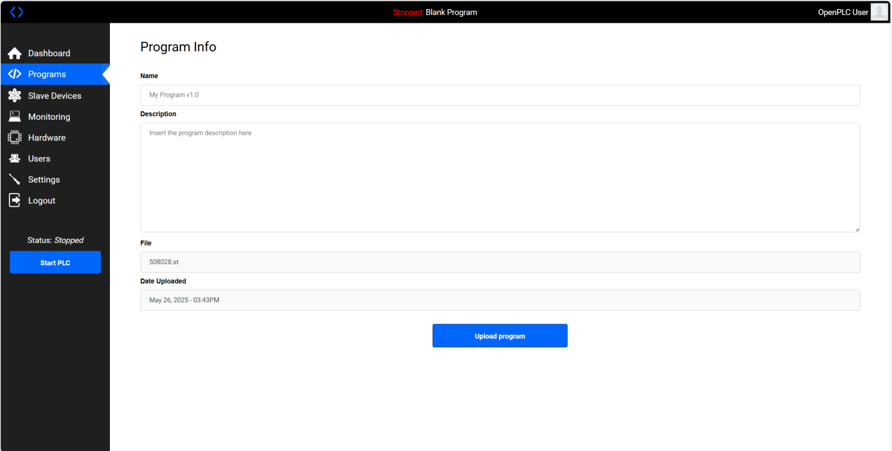
5. We need to set the project name, otherwise the PLC program cannot run properly.
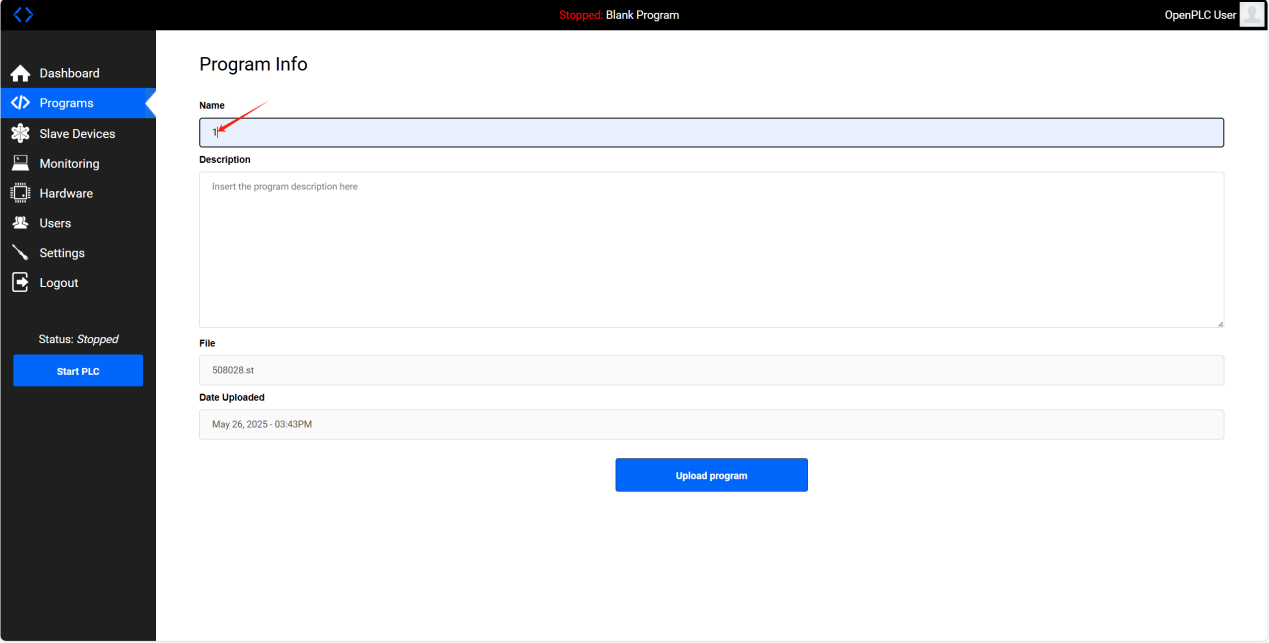
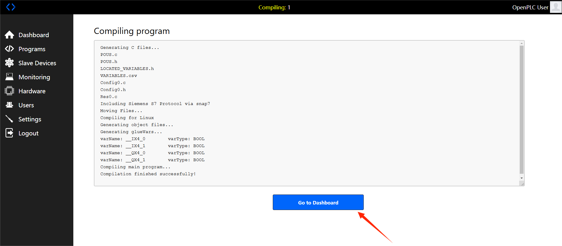
6. Click "upload program" below, wait for a moment, and click "go to dashboard" below when it becomes clickable.
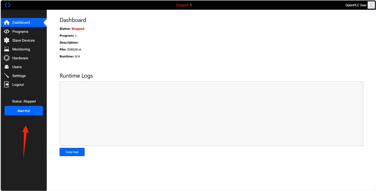
7. "start plc" appears in the progress bar on the left.
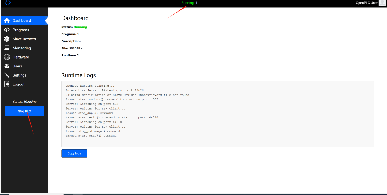
8. Click "start plc" to run the PLC. Under normal circumstances, the status at the top will display "running". If it does not display in time, please wait for a while or refresh the interface. If it fails to start all the time, you can click "start plc" again. If there is an error, please check the correctness of the PLC program.
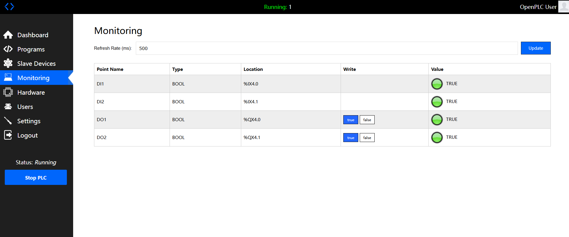
9. Click on "monitoring" in the left navigation bar to observe the current status of the contact coil.
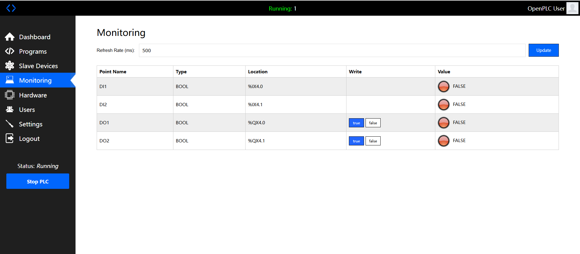
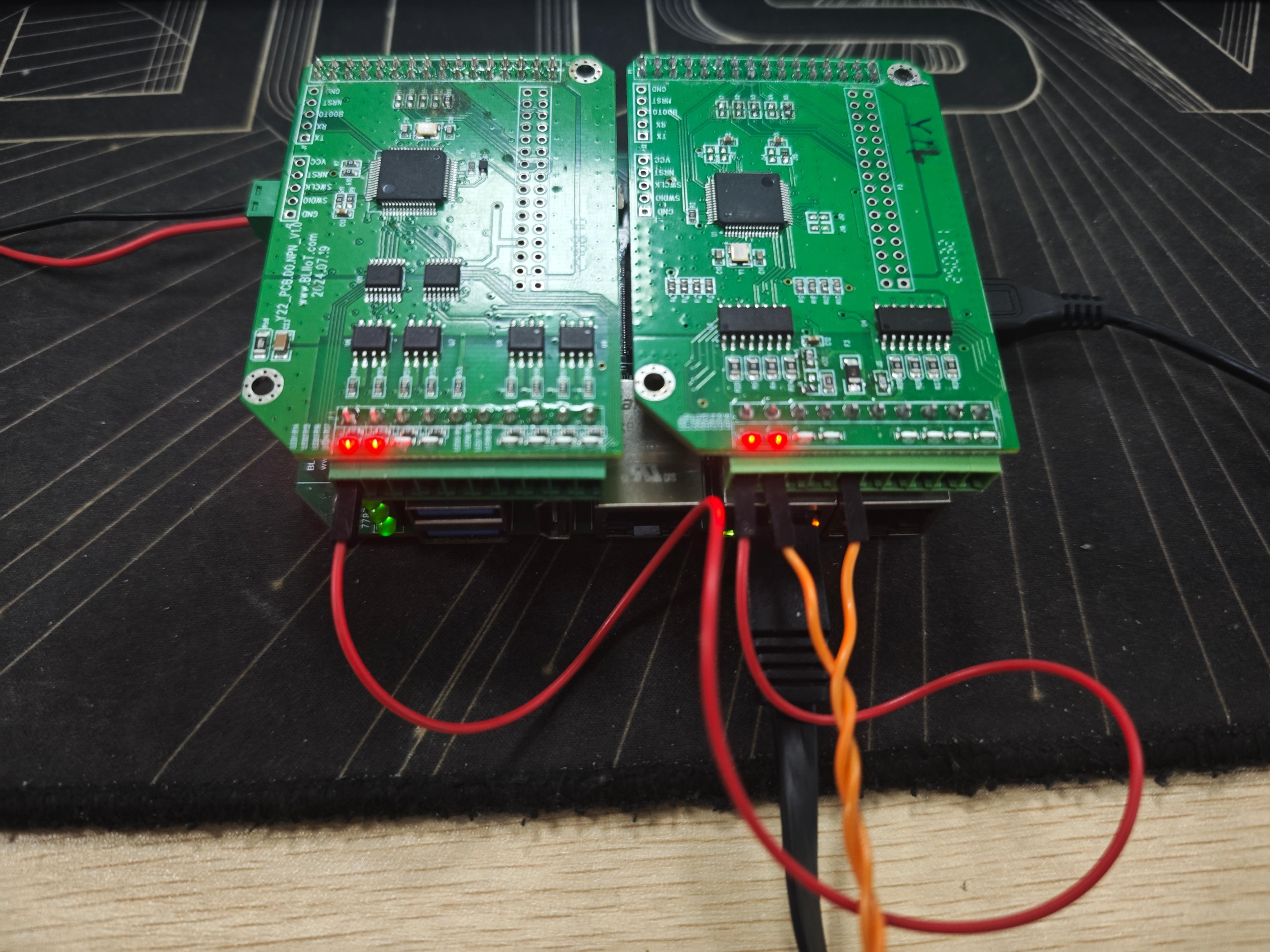
10. The running result of the above example program is shown in the figure below (taking BL450 used with Y22 and Y12 as an example):
Other matters
1. Usage of openplc with BLRAT
Please refer to the BLRAT usage method. Using the IP assigned by BLRAT allows for remote network uploading of programs and device detection.
2. Coil mapping relationship of openplc
OpenPLC currently supports all X boards and Y boards, except for some boards that do not have DI, DO, or do not have AI, AO.
Explanation of mapping rules: PLC coils are grouped into sets of 8, with the usage format %aXb.c (where a represents different types, X is fixed as uppercase; for example, I represents input, b represents which group, and c represents which coil in that group).
a. X board: DI starts from the second coil of the first group. For example, DI1 is %IX0.1, and the subsequent ones follow in order. For example, for DI9, the corresponding coil is calculated as follows: 9 divided by 8 equals 1 with a remainder of 1, so the coil is %IX1.1. The corresponding relationship of DO is the same as that of DI. For example, the coil represented by DO0 is %QX0.1
b. Y-board: The corresponding relationship of the Y-board is to first scan the Y-board corresponding to the X5 resistor, find DI, DO, AI, and AO, then find the DI, DO, AI, and AO corresponding to the X4 resistor. Therefore, the board corresponding to the X5 resistor comes first, and the board corresponding to the X4 resistor comes later in sequence. The coils of the Y-board start from 17, that is, 17 divided by 8 leaves a remainder of 1, which refers to the DI coil of the Y-board. For example, channel 3001 is the first DI, corresponding to %IX2.1, and scanning proceeds sequentially backward; the same applies to DO. It should be noted that a special case of the Y-board is that it has AI and AO. The PLC itself supports analog input, so mapping processing has also been carried out, where %IW represents AI and %QW represents AO. The starting position also begins from 17, for example, AO1 is %IW17, and AO is similar.
c. With the above two rules, when users use our N board, which is an IO expansion board, the mapping rule starts from 64, and the usage method is the same as above.


